Flex Sensor 2.2″
1,400.00 ৳
In stock
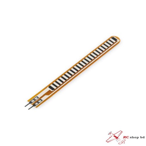
Flex Sensor 2.2″ Inch Bend Flex Sensor For Robotic Hand Electronic Gloves Flex2.2 Flex Sensor Pressure Sensor Resistive Flex Sensor Robotic Arm Power Glove Measuring Bending DIY
A flex sensor or bend sensor is a sensor that measures the amount of deflection or bending. Usually, the sensor is stuck to the surface, and the resistance of the sensor element is varied by bending the surface. Since the resistance is directly proportional to the amount of bend it is used as a goniometer, and often called a flexible potentiometer.
This Sensor 2.2 inch in Pakistan is a simple flex sensor 2.2″ in length. As the sensor is flexed, the resistance across the sensor increases. Patented technology by Spectra Symbol – they claim these sensors were used in the original Nintendo Power Glove. I love the Nintendo Power Glove. The resistance of the bend sensor changes when the metal pads are on the outside of the bend (the text on inside of end) Connector is 0.1″ spaced and breadboard friendly. Check the datasheet for full specifications.
Note: Please refrain from flexing or straining this sensor at the base. The usable range of the sensor can be flexed without a problem, but care should be taken to minimize flexing outside of the usable range. For best results, securely mount the base and bottom portion and only allow the actual flex sensor to flex.
Specifications:
- Operating voltage of FLEX SENSOR: 0-5V
- Can operate on LOW voltages
- Power rating : 0.5Watt (continuous), 1 Watt (peak)
- Life: 1 million
- Operating temperature: -45ºC to +80ºC
- Flat Resistance: 25K Ω
- Resistance Tolerance: ±30%
- Bend Resistance Range: 45K to 125K Ohms(depending on bend)
Dimensions:
- Length (all sensor): 73.66 mm (3″)
- Length (active part): 55.37 mm (2.2″)
- Width: 6.41 mm
- Thickness: 0.48 mm
- Weight: 0.27 gr
Features:
- Angle Displacement Measurement
- Bends and Flexes physically with motion device
- Possible Uses
- Simple Construction
- Low Profile
- Physical Therapy
- Musical Instruments
- Computer Peripherals
- Medical Devices
- Gaming (Virtual Motion)
- Robotics
Where to Use FLEX SENSOR
For understanding the use of FLEX SENSOR consider:
Case1: Where you want to check whether the surface of a device or thing is leveled or not. Say you want a device to check whether a window or door is open or not. At that time a Flex sensor could be used. The sensor could be fixed at door edge and when the door opens the Flex sensor gets flexed. With the sensor being flexed its parameters changes which could be designed to provide an alert.
Case2: Where you want to measure the FLEX or BENT or ANGLE change of any instrument or device. The FLEX SENSOR internal resistance changes almost linearly with its flex angle. So by sticking the sensor to the instrument, we can have the flex angle in electrical parameter of resistance.
How to Use FLEX SENSOR
As mentioned earlier, FLEX SENSOR is basically a VARIABLE RESISTOR whose terminal resistance increases when the sensor is bent. So this sensor resistance increases depends on surface linearity. So it is usually used to sense the changes in linearity.
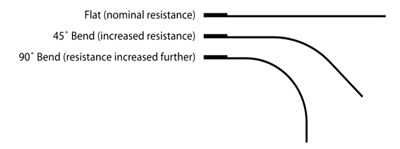
As shown in the above figure, when the surface of FLEX SENSOR is completely linear it will be having its nominal resistance. When it is bent 45º angle the FLEX SENSOR resistance increases to twice as before. And when the bent is 90º the resistance could go as high as four times the nominal resistance. So the resistance across the terminals rises linearly with bent angle. So in a sense the FLEX sensor converts flex angle to RESISTANCE parameter.
For convenience we convert this RESISTANCE parameter to VOLTAGE parameter. For that we are going to use VOLTAGE DIVIDER circuit. A typical VOLTAGE DIVIDER circuit is shown below.
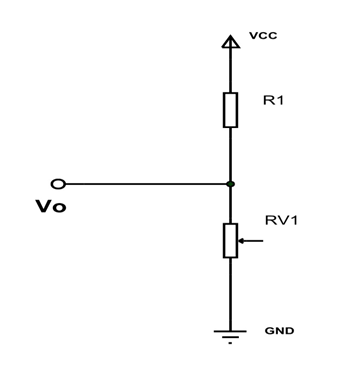
In this resistive network we have two resistances. One is constant resistance (R1) and other is variable resistance (RV1). Vo is the voltage at midpoint of VOLTAGE DIVIDER circuit and is also the output voltage. Vo is also the voltage across the variable resistance (RV1). So when the resistance value of RV1 is changed the output voltage Vo also changes. So we will have resistance change in voltage change with VOLTAGE DIVIDER circuit.
Here we will replace the variable resistance (RV1) with FLEX SENSOR. The circuit will be as below.
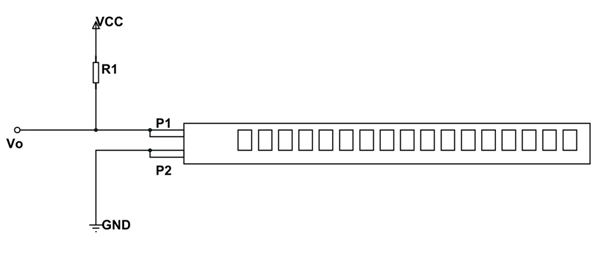
As shown in figure, R1 here is a constant resistance and FLEX SENSOR which acts as a variable resistance. Vo being output voltage and also the voltage across the FLEX SENSOR.
Here,
Vo = VCC (Rx/ (R1+Rx)).
Rx – FLEX SENSOR resistance
Now, when the FLEX SENSOR is bent the terminal resistance increases. This increase also appears in VOLTAGE DIVIDER circuit. With that the drop across the FLEX SENSOR increases so is Vo. So with increase in bent of FLEX sensor Vo voltage increases linearly. With that we have VOLTAGE parameter representing the flex.
We can take this VOLTAGE parameter and feed it to ADC to get the digital value which can be used conveniently.
Applications
- Robotics
- Gaming (Virtual Motion)
- Medical Devices
- Computer Peripherals
- Musical Instruments
- Physical Therapy
Package Include:
- 1 x Flex Sensor 2.2″

