L293D Motor Driver Shield
220.00 ৳
In stock
Description:
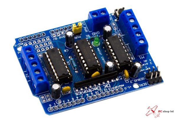
L293D Motor Driver/Servo Shield for Arduino
This Arduino compatible motor Driver shield is a full-featured products that it can be used to drive 4 DC motors or two 4-wire stepper and two 5V ”hobby” servo. It drive the DC motor and stepper with the L293D, and it drive the servo with Arduino”s pin9 and pin10.
L293D is a monolithic integrated, high voltage, high current, 4-channel driver.
Basically this means using this chip you can use DC motors and power supplies of up to 10 Volts, thats some pretty big motors and the chip can supply a maximum current of 600mA per channel, the L293D chip is also what’s known as a type of H-Bridge.
Features:
Brand new and high quality.
L293D is a monolithic integrated, high voltage, high current, 4-channel driver.
Basically this means using this chip you can use DC motors and power supplies of up to 10 Volts, thats some pretty big motors and the chip can supply a maximum current of 600mA per channel, the L293D chip is also what’s known as a type of H-Bridge.
The H-Bridge is typically an electrical circuit that enables a voltage to be applied across a load in either direction to an output, e.g. motor.
2 interface for 5V Servo connected to the Arduino’s high-resolution dedicated timer – no jitter.
Can drive 4 DC motors or 2 stepper motors or 2 Servo.
Up to 4 bi-directional DC motors with individual 8-bit speed selection.
Up to 2 stepper motors (unipolar or bipolar) with single coil, double coil or interleaved stepping.
4 H-Bridges: per bridge provides 0.6A (1.2A peak current) with thermal protection, can run motors on 4.5V to 10V DC.
Pull down resistors keep motors disabled during power-up.
reset button.
2 external terminal power interface, for seperate logic/motor supplies.
Tested compatible for Arduino Mega, Diecimila & Duemilanove.
Size:6.8cm x 5.5cm x 2cm – 2.68inch x 2.17inch x 0.79inch.
Screw-Terminal blocks for connection to motors
External power connection via a screw-terminal block
Motor Supply Voltage: 4.5 ~ 12V
2 x L293D Motor Control Chips
Total of 4 H-Bridges for controlling 4 DC motors or 2 Stepper motors
2 x Server ports for controlling RC Hobby Servos
The logic control voltage Vss: 4.5~5.5V
Reduced control pins needed through 8-stage serial shift registers
Drive part of the operating current Io: 1.2A (0.6A per bridge)
Specifications:
L293D is a monolithic integrated, high voltage, high current, 4-channel driver
Basically this means using this chip you can use DC motors and power supplies of up to 36 Volts, that’s some pretty big motors and the chip can supply a maximum current of 600mA per channel
L293D chip is also what’s known as a type of H-Bridge
The H-Bridge is typically an electrical circuit that enables a voltage to be applied across a load in either direction to an output, e.g. motor
2 interface for 5V Servo connected to the Arduino”s high-resolution dedicated timer – no jitter
Can drive 4 DC motors or 2 stepper motors or 2 Servo
Up to 4 bi-directional DC motors with individual 8-bit speed selection
Up to 2 stepper motors ( unipolar or bipolar) with single coil, double coil or interleaved stepping
4 H-Bridges: per bridge provides 0.6A (1.2A peak current) with thermal protection, can run motors on 4.5V to 36V DC
Pull down resistors keep motors disabled during power-up reset button
2 external terminal power interface, for seperate logic/motor supplies
Tested compatible for Arduino Mega, Diecimila & Duemilanove
Drive 4 DC motors with speed and direction control
Drive 2 stepper motors
4.5 – 25V motor voltage range
1.2A peak current per channel (600mA continuous)
The L293D V1 Motor Shield can drive up to 4 DC motors at voltages from 4.5 – 25V and at currents of up to 1.2A peak (600mA continuous) per motor with speed and direction control.
The module can also support up to 2 stepper motors. Each stepper motor takes the place of 2 of the DC motors, so you can run 2 stepper motors or 1 stepper motor and 2 DC motors or 4 DC motors.
The shield also technically supports 2 servo motors for which there are two 3-pin headers on the module. Unfortunately it powers the servo motors directly off the Arduino 5V which is never a good idea. Doing so can overheat the Arduino on-board 5V regulator as well as induce electrical noise into the Arduino 5V power causing intermittent problems that are difficult to troubleshoot, therefore it is not recommended to use this feature. If you are a hacker, the traces to the 5V center pins on the servo headers can be easily cut and rewired to a separate 5V power source.
Motor Power Connections:
Motor voltage must be between 4.5 – 25V. This power can be shared with the Arduino or be separate. To select this, there is a jumper near the 2 terminal power connector labeled PWR.
When this jumper is installed, the power from the Arduino DC power jack is also connected to the motors. Vin (marked 9V on the board) is brought up form the Arduino to power the motors.
When the jumper is removed, that isolates the motor power from the Arduino and it must be supplied separately by connecting power to the 2 terminal power connector. Note: Do not apply power to the 2 terminal power connector with the jumper in place or it will short the two power supplies together!
1 x 2 Terminal EXT_PWR (Motor Power)
+M = Motor Vcc which must be between 4.5 and 25V.
GND = Motor Ground.
DC Motor Connections:
The motor connections are via two screw terminals for each motor and labeled M1 thru M4. The center terminal on the 5-pos terminal blocks are connected to ground.
The wiring of which lead of the motor connects to which terminal is somewhat arbitrary and relative to what you consider forward vs reverse motor operation. If the motor goes in the opposite direction that you expect, simply reverse the wiring.
1 x 2 Terminal M1 – M4 (DC Motor 1-4)
Motor ‘-‘ positive lead
Motor ‘+’ negative lead
Stepper Motor Connections:
Stepper motors are typically 4 wire. Coil 1 will connect across one motor port such as M1 (M3) and coil 2 will connect across the other motor port such as M2 (M4). If the stepper motor has 5 wires, the center tap wire will be connected to the center ground terminal.
1 x 2 Terminal M1(M3) – M2(M4) (Servo Motor 1-2)
Motor Coil 1
Motor Coil 2
Arduino to Shield Pin Connections:
The shield has a remote reset button located on it for easy access.
The shield uses Pins D3,D4, D5, D6, D7, D8, D11 and D12 for DC and stepper motor control.
D9 and D10 come out to the Servo headers.
The other pins are available including the 6 analog pins that can also be used as digital I/O. These have solder pads so that a header can be added if desired for easy connections. Next to that is a row of 5V and Ground connections that can also be populated with headers if desired.
Package Include:
1 x L293D V1 Motor Shield

