

QTR-8RC Reflectance IR Sensor Array
350.00 ৳
In stock
QTR-8RC Reflectance IR Sensor Array
This sensor module has 8 IR LED/phototransistor pairs mounted on a 0.375″ pitch, making it a great detector for a line-following robot. Pairs of LEDs are arranged in series to halve current consumption, and a MOSFET allows the LEDs to be turned off for additional sensing or power-savings options. Each sensor provides a separate digital I/O-measurable output.
The QTR-8RC reflectance sensor array is intended as a line sensor, but it can be used as a general-purpose proximity or reflectance sensor. The module is a convenient carrier for eight IR emitter and receiver (phototransistor) pairs evenly spaced at intervals of 0.375″ (9.525 mm). To use a sensor, you must first charge the output node by applying a voltage to its OUT pin. You can then read the reflectance by withdrawing that externally applied voltage on the OUT pin and timing how long it takes the output voltage to decay due to the integrated phototransistor. Shorter decay time is an indication of greater reflection. This measurement approach has several advantages, especially when coupled with the ability of the QTR-8RC module to turn off LED power:
- No analog-to-digital converter (ADC) is required
- Improved sensitivity over voltage-divider analog output
- Parallel reading of multiple sensors is possible with most microcontrollers
- Parallel reading allows optimized use of LED power enable option
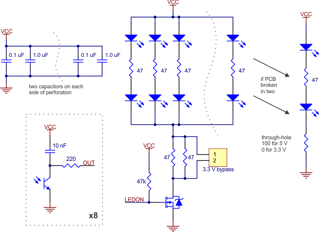
The outputs are all independent, but the LEDs are arranged in pairs to halve current consumption. The LEDs are controlled by a MOSFET with a gate normally pulled high, allowing the LEDs to be turned off by setting the MOSFET gate to a low voltage. Turning the LEDs off might be advantageous for limiting power consumption when the sensors are not in use or for varying the effective brightness of the LEDs through PWM control.
This sensor was designed to be used with the board parallel to the surface being sensed.
The LED current-limiting resistors for 5 V operation are arranged in two stages; this allows a simple bypass of one stage to enable operation at 3.3 V. The LED current is approximately 20–25 mA, making the total board consumption just under 100 mA. The schematic diagram of the module is shown below:
 |
For a similar array with three sensors, consider our QTR-3RC reflectance sensor array. The sensors on the QTR-8RC are also available individually as the QTR-1RC reflectance sensor, and the QTR-L-1RC is an alternative designed to be used with the board perpendicular to the surface.
Specifications
- Dimensions: 2.95″ x 0.5″ x 0.125″ (without header pins installed)
- Operating voltage: 3.3-5.0 V
- Supply current: 100 mA
- Output format: 8 digital I/O-compatible signals that can be read as a timed high pulse
- Optimal sensing distance: 0.125″ (3 mm)
- Maximum recommended sensing distance: 0.375″ (9.5 mm)
- Weight without header pins: 0.11 oz (3.09 g)
Interfacing the QTR-8RC Outputs to Digital I/O Lines
The QTR-8RC module has eight identical sensor outputs that, like the Parallax QTI, require a digital I/O line capable of driving the output line high and then measuring the time for the output voltage to decay. The typical sequence for reading a sensor is:
- Turn on IR LEDs (optional).
- Set the I/O line to an output and drive it high.
- Allow at least 10 μs for the sensor output to rise.
- Make the I/O line an input (high impedance).
- Measure the time for the voltage to decay by waiting for the I/O line to go low.
- Turn off IR LEDs (optional).
Related products
-
Add to cart
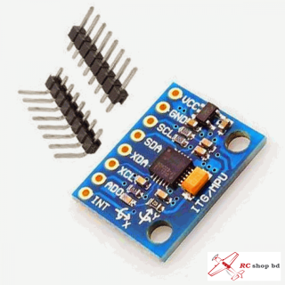
6DOF MPU6050 3 Axis Gyro & Accelorometer Name: MPU-6050 module (three-axis gyroscope + triaxial accelerometer) 2.54mm pin spacing MPU-6050 Accelerometer + Gyro The MPU-6050 sensor contains a MEMS accelerometer and a MEMS gyro in a single chip. It is very accurate, since it contains 16-bits analog to digital conversion hardware for each channel. Therefor it …
-
 Add to cart
NodeMcu Lua ESP8266 Board with CP2102 SP8266 is a highly integrated chip designed for the needs of a new connected world. It offers a complete and self-contained Wi-Fi networking solution, allowing it to either host the application or to offload all Wi-Fi networking functions from another application processor. Features: 1. Open-source 2. Interactive 3. Programmable …
-
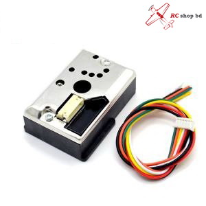
Dust Sensor
850.00 ৳Add to cartDust Sensor Dust Sensor, A simple Air Monitor Overview Sharp GP2Y1010AU0F onboard, detecting fine particle larger than 0.8μm in diameter, even like the cigarette smoke Low power consumption, analog voltage output, the output level is linear with dust density Embedded voltage boost circuit to support wide range of power supply Specifications Sensitivity : 0.5V/(100μg/m3) Measurement …
-
Add to cart
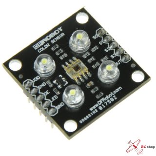
The TCS3200 Color Sensor Module uses a high-quality light sensor allowing you to sense any color through a combination of Red, Green, and Blue. The module provides all of the pins of the TCS3200 on convenient 0.1″ headers – ideal for use with PCBs, breadboard or strip board. The module requires only a single supply …
-
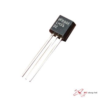
LM35 Temperature Sensor
80.00 ৳Add to cartThe LM35 Temperature Sensor are precision integrated-circuit temperature sensors, whose output voltage is linearly proportional to the Celsius or Centigrade temperature. The LM35 thus has an advantage over linear temperature sensors calibrated in Kelvin. the user need not do any external calibration or trimming to provide typical accuracies of ±1⁄4C at room temperature and ±3⁄4C …
-
HC-06 bluetooth module
370.00 ৳Add to cartThis is a bluetooth module for use with any microcontroller. It uses the UART protocol to make it easy to send and receive data wirelessly. The HC-06 module is a slave only device. This means that it can connect to most phones and computers with bluetooth but it cannot connect to other slave only devices …